Voltage drop across inductor calculator
The capacitance voltage vector V C leads the current in the capacitor vector by 90 and it is drawn at 90. For a pure inductor this phase angle will be 90 or ¼ of a cycle.

Ac Inductance And Inductive Reactance In An Ac Circuit
The charge pump MOSFET driver ensures that the MOSFET saturates and gets the voltage it needs to fully conduct and have the lowest possible on-resistance for lesser power losses in the buck Vgs are usually.

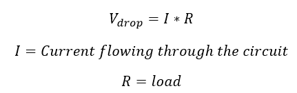
. The flow of current through the series circuit is I VR according to Ohms Law. This means that V out is equal to V in at high frequencies. IR1 VR1.
The impedance phase angle for any component is the phase shift between the voltage across that component and current through that component. Then you can set up the current monitors and begin your measure. Total time for dissipation may vary but it will last for a few milliseconds.
This happens when the MOSFET is provided with a lower voltage across the gate and source pin from the specified Vth threshold voltage. A Boost Converter takes an input voltage and boosts it. By using Kirchoffs voltage law total voltage drop is the sum of the voltage drop across each inductor.
It will resist the sudden change of current. The vector sum of the two opposing vectors can be pointed downwards or upwards depending on the voltage drop across the inductor and the capacitor. However it should be noted that the fundamental 5060Hz voltage drop across the Line reactor will be a small valueThe reason for this is that drives are inherently high displacement power factor devices Fundamental.
The vector sum of the two opposing vectors can be pointed downwards or upwards depending on the voltage drop across the inductor and the capacitor. AC Voltage drop. Adjunct membership is for researchers employed by other institutions who collaborate with IDM Members to the extent that some of their own staff andor postgraduate students may work within the IDM.
A capacitor inductor or the two in combination. The voltage drop of this IC is similar to a resistor voltage drop. Inductor current lags inductor voltage by 90.
So now can calculate the voltage drop across the R2 resistor in the circuit. If an alternating sine voltage is applied across a coil the current will lag behind the voltage by some phase angle as shown in the picture. An inductor typically consists of an insulated wire wound into a coil.
The inductor circuit offers high impedance to high-frequency signals and hence can be considered as an open circuit. For low-frequency signals it offers little to no resistance and hence the voltage drop across it is negligible resulting in a low output voltage. According to Kirchhoffs Voltage Law The voltage around a loop equals the sum of every voltage drop in the same loop for any closed network and equals zero.
To measure inductance on a voltage current slope connect the inductor coil to a pulsed voltage source and keep the pulse below 50 percent. The output waveform has been clipped at -V f -7 volts during negative half-cycles because the voltage across the diode is. We know that in inductor voltage leads current by 90 o so draw V L voltage drop across inductor perpendicular to current phasor.
In this case the current flowing through each inductor is the same while the voltage across each inductor is different. Perfect resistor inductor and capacitor. Ie V R is in phase with I.
A boost converter step-up converter is a DC-to-DC power converter that steps up voltage while stepping down current from its input supply to its output load. With our money back guarantee our customers have the right to request and get a refund at any stage of their order in case something goes wrong. The voltage across the inductor has a phase angle of 52984 while the current through the inductor has a phase angle of -37016 a difference of exactly 90 between the two.
When the current flowing through the coil changes the time-varying magnetic field induces an electromotive force emf in the. V T V 1. Remember the voltage dropped across an inductor is a reaction against the change in current through it.
An inductor also called a coil choke or reactor is a passive two-terminal electrical component that stores energy in a magnetic field when electric current flows through it. The efficiency of the regulator can be restricted to 3V or 5V which means these regulators are applicable with fewer Vin Vout differentials. Voltage Drop Calculation For DC direct current power system.
The voltage across the resistor has the exact same phase angle as the current through it telling us that E and I are in phase for the resistor only. Here three inductors and are connected in series. So draw the voltage phasor V R along same axis or direction as that of current phasor.
Vs R1R2 VR2 Vs R2 R1R2 Similarly the voltage drop across the R1 resistor can be calculated as. For example when the input of the voltage regulator is 5V generates output like 3V then the voltage drop among the two terminals is 2V. The capacitance voltage vector V C leads the current in the capacitor vector by 90 and it is drawn at 90.
Here the voltage is sinusoidal in nature and is given by the equation Here v m is the amplitude of the voltage and ω is the frequency. For a perfect resistor the voltage drop and current are always in phase with each other and so the impedance angle of a resistor is said to be 0. Working and Circuit diagram of a boost converter.
This voltage depends upon the inductance value. Pure inductive circuit waveforms. At the point on the time axis ωt π2 in which the current is zero there is a positive maximum voltage across the inductor.
Freewheel diode or Flyback diodes are basically connected across inductive coils to prevent from voltage spikes in case of power getting turned off to the devices. The voltage drop across this conducting path is equal in magnitude but opposite polarity i from that of a positive clipper circuit. For 3-year terms which are renewable.
This tells us. The voltage across the inductor will be a function of the forward voltage drop of the Flyback diode. It is a class of switched-mode power supply SMPS containing at least two semiconductors a diode and a transistor and at least one energy storage element.
In DC power system we can calculate voltage drop across the conductor by using basic ohms law formula. The total voltage vector V T is obtained using Pythagoras theorem. Line Reactor create a voltage drop due to the very nature of an inductor ie.
In other words its like a step up transformer ie it step up the level of DC voltage while transformer step up down the level of AC voltage from low to high while decreases the current from high to low while the supplied power is same. If we were to plot the current and voltage for this very simple circuit it would look something like this. So the flow of current is the same in both resistors.
Consider the circuit shown above. Youll need to read the peak current in amperes and the amount of time between voltage pulses in microseconds. Also using Kirchhoffs circuit laws Voltage and current You can find the sum of the voltage drops across each component of the circuit is equal to the supply voltage.
Put differently the algebraic sum of every voltage in the loop has to be equal to zero and this property of Kirchhoffs law is called conservation of energy. Here we have an inductor a resistor and a capacitor connected through a series connection across an AC voltage source given by V. In case of resistor both voltage and current are in same phase.
The electrical resistance of an object is a measure of its opposition to the flow of electric currentIts reciprocal quantity is electrical conductance measuring the ease with which an electric current passesElectrical resistance shares some conceptual parallels with mechanical frictionThe SI unit of electrical resistance is the ohm while electrical conductance is.

Potential Difference And Resistor Voltage Division

Inductive Reactance Reactance Of An Inductor

Calculating Voltages In Complex Series Rlc Circuits Youtube

Voltage Across Inductor Bartleby

Can The Voltage Drop Across The Inductor Or Capacitro In A Series Lcr Circuit Be Greater Than Youtube

Voltage Dividers And Voltage Division Circuits

Can The Voltage Drop Across The Inductor Or Capacitro In A Series Lcr Circuit Be Greater Than Youtube

Voltage Dividers And Voltage Division Circuits

Ac Voltage Across Pure Inductor Derivation Video Khan Academy
Pin On Electronic Circuits

Capacitors In Series And Series Capacitor Circuits

How To Calculate The Voltage Across An Inductor
What Is Voltage Drop Allowable Limit And Calculation Electrical4u

Voltage And Current Calculations Of Inductor

Inductor Impedance Calculator Electrical Rf And Electronics Calculators Online Unit Converters

Magnetic Polarity Detector Circuit Diagram Circuit Diagram Electronic Organization Electronics Circuit
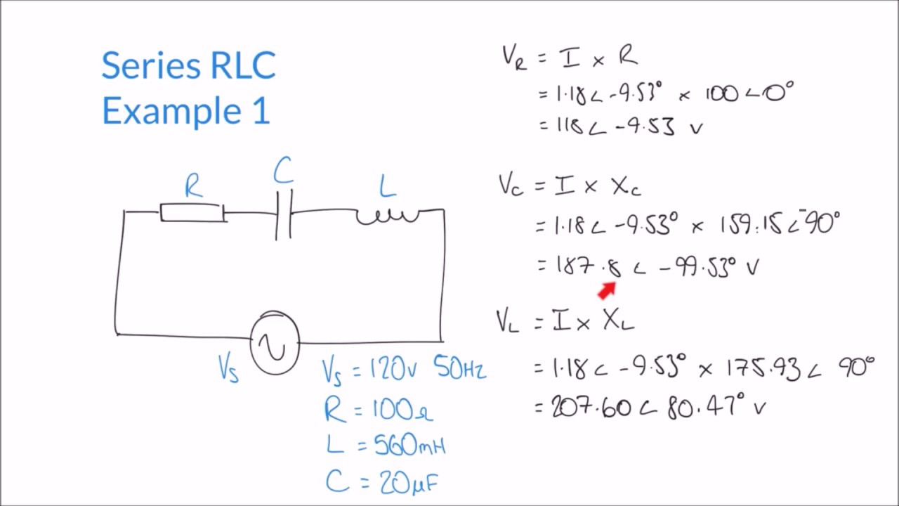
Calculating Impedance Supply Current And Voltages In Series Rlc Circuit Youtube